 |
|
Please Whitelist This Site?
I know everyone hates ads. But please understand that I am providing premium content for free that takes hundreds of hours of time to research and write. I don't want to go to a pay-only model like some sites, but when more and more people block ads, I end up working for free. And I have a family to support, just like you. :)
If you like The TCP/IP Guide, please consider the download version. It's priced very economically and you can read all of it in a convenient format without ads.
If you want to use this site for free, I'd be grateful if you could add the site to the whitelist for Adblock. To do so, just open the Adblock menu and select "Disable on tcpipguide.com". Or go to the Tools menu and select "Adblock Plus Preferences...". Then click "Add Filter..." at the bottom, and add this string: "@@||tcpipguide.com^$document". Then just click OK.
Thanks for your understanding!
Sincerely, Charles Kozierok
Author and Publisher, The TCP/IP Guide
|
|
|

Custom Search
|

|


OSPF Hierarchical Topology, Areas and Router Roles
(Page 3 of 3)
OSPF Hierarchical Topology Example
I'm sure this all made perfect sense the first time you read it. Uh-huh. J Let's take an example to help make things more concrete. We can use the autonomous system in the preceding topic. This AS is really small enough that it's unlikely one would use hierarchical topology, but it will suffice for sake of illustration. Let's divide this AS into two areas, as follows (see Figure 180):
- Area 1: This area would contain N1,
RA, N2, RB and RC.
- Area 2: This area would contain RB,
RC, N3, RD and N4.
Figure 180: Example OSPF Hierarchical Topology Autonomous System
This is the same AS we saw in Figure 179 but arranged into OSPF hierarchical topology. The AS has been split evenly into Area 1 and Area 2. Area 0 contains RB and RC, which are area border routers for both Area 1 and Area 2 in this very simple example AS.
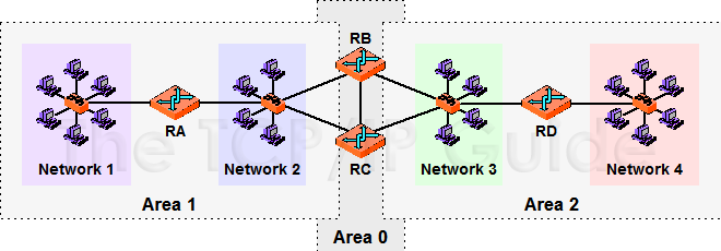
In this example, Router A and Router D are internal routers. Router B and Router C are area border routers, and comprise the backbone (Area 0) of the internetwork. Routers A, B and C will maintain an LSDB describing Area 1, while Routers B, C and D will maintain an LSDB describing Area 2. Routers B and C maintain a separate LSDB for the backbone. There is no backbone router other than the area border routers B and C. However, suppose we had a router E that had only direct connections to RB and RC. This would be a backbone router only.
You have probably already discovered the chief drawback to hierarchical topology: complexity. For large autonomous systems, however, it has significant advantages over making every router a peer. At the same time, the conceptual complexity is made worse by the need for very careful design, especially of the backbone. If the hierarchy is not set up properly, a single failure of a link between routers could disrupt the backbone and isolate one or more of the areas (including all the devices on all networks within the area!)
|
| |||||||||||||||||||
Home - Table Of Contents - Contact Us
The TCP/IP Guide (http://www.TCPIPGuide.com)
Version 3.0 - Version Date: September 20, 2005
© Copyright 2001-2005 Charles M. Kozierok. All Rights Reserved.
Not responsible for any loss resulting from the use of this site.